xxx
I will tell you about a fault I had with a Recel System 3 pinball machine, one I had been carrying around for a long time.
One fine day the machine began to emit a low-frequency vibration coming from the relay on the power-supply board, the relay driven by the "in play" signal.
Apart from the annoyance of the noise, the most troublesome consequence was a loss of power at the flippers. The relay controls the 44 V supply to the coils. By chattering—making and breaking contact at about 50 Hz—the available power to the coils was roughly halved.
The first thing to have done would have been to look at the waveform of the 7.5 V supply after rectification from the transformer. But that is not terribly convenient, and it was so much simpler to blame the relay at first glance. It’s forty years old; it has lived its life. Let’s replace it.
First question: what pull-in voltage for that relay? 6 V or 9 V? Fine, order both and we’ll see…
After replacement (and choosing the 9 V version), the machine resumed normal operation… for about twenty minutes.
A word on relay types. There are essentially two pin patterns: one with pins at right angles, and another with the secondary pins set a little diagonally. Better to take the right-angle pin model, which is the original footprint. Otherwise you can make it work by mounting the relay on a piece of vero board and improvising a solution—but it’s fiddly. It cost me half a day. Not to mention that working on that board is no picnic. Be careful not to finish ruining the solder joints of the already tired wires coming from the transformer. Check them carefully after you’re done. If not, you’ll be rewarded with more faults on other supply rails for sure.
After twenty minutes, the buzzing returned with a vengeance.
Following the adage "replace things at random rather than think," I assumed the relay driver transistor must be at fault — an NPN, SC107 with an unusual pinout. After swapping it for a BC337 and bending the leads to fit an SC107 footprint, guess what happened… No improvement.
At this point you’re thinking he must have hooked up an oscilloscope or something… Of course I did not!
I preferred to make conjectures about the root cause. Since the vibration resembled a 50 Hz frequency, the problem could only be the filter capacitor, naturally!
So I replaced the capacitor, labeled 220K. Which, frankly, tells you little… 220 nF, 220 µF? I didn’t have the right part anyway. A 1 µF electrolytic would do.
No change. Neither better nor worse.
At that stage I finally measured the voltage. Unloaded: 9 V. Under load: 2.88 V.
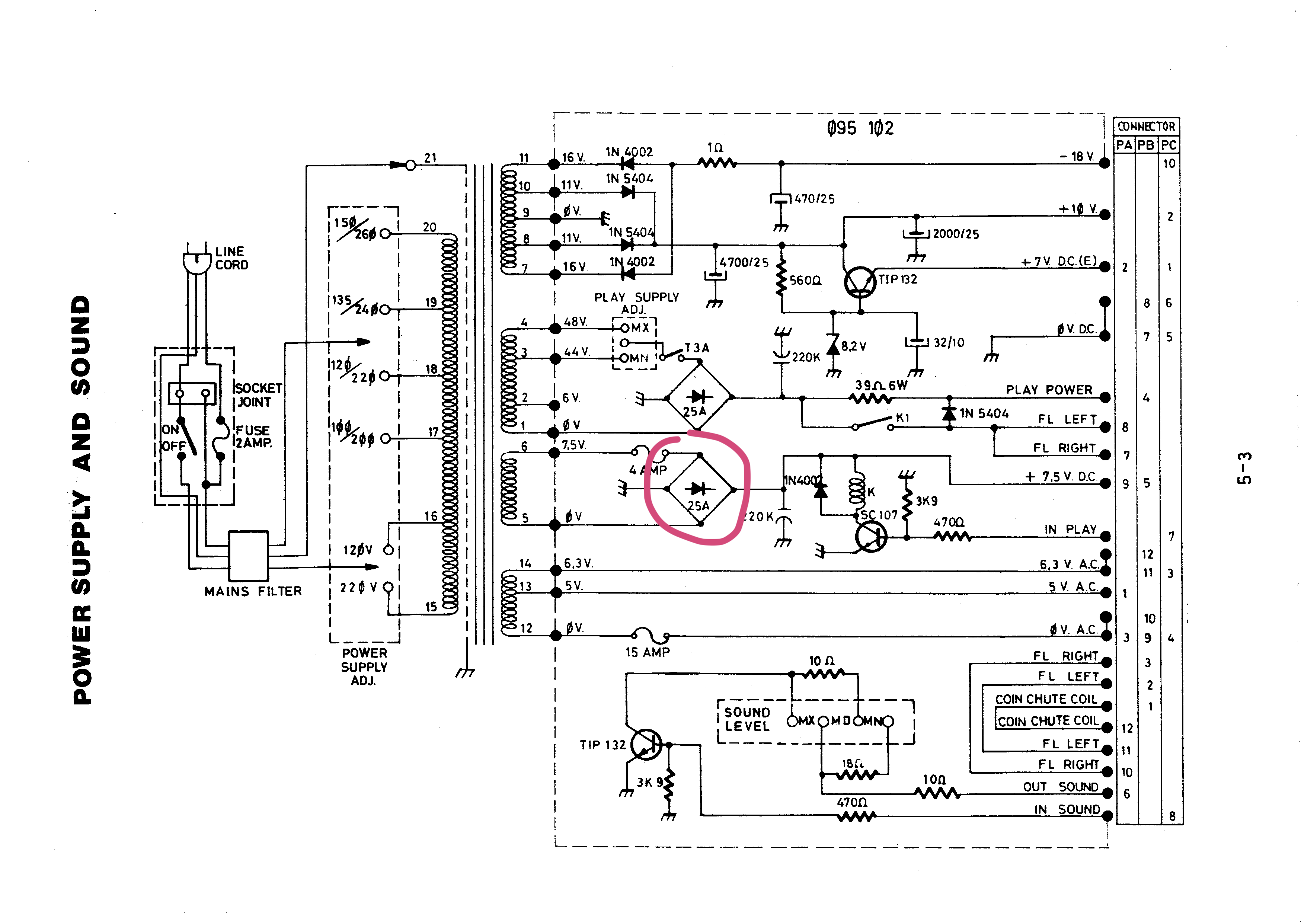
Was it really necessary to measure at that point, given that I had already changed everything except the diode bridge? The bloody blasted DIODE BRIDGE. Marked 25 A.
So, order a 25 A diode bridge. Besides, the general documentation seems unanimous that aging bridge rectifiers, once run hot, show large voltage drops across the diodes under heavy load.
Replacing the diode bridge (not easy—an awful lot of solder to desolder) and, of course, everything worked perfectly. The lamps driven by the MPU (the flashing lamps and the bonus lamps) had never shone so brightly. They are fed by the same 7.5 V source, as is the coin chute coil.
Problem solved, then—after two years.
Conclusion: If you have power-supply troubles, always measure the output voltages both under load and unloaded; if there is a large discrepancy, suspect first the diode bridge, or possibly an old solder joint somewhere on the board acting as a resistor and causing a severe voltage drop as current increases.